
DDM
-
installation between flanges as per DIN EN 1092-1
-
internal and external threads as per DIN EN ISO 228
-
pipe union as per DIN EN 10226-1 (ISO 7-1)
-
calibrated to customer specifications for liquids and gases
-
horizontal or vertical installation
-
no wear, no moving parts
-
accuracy 2,5% of full-scale range
-
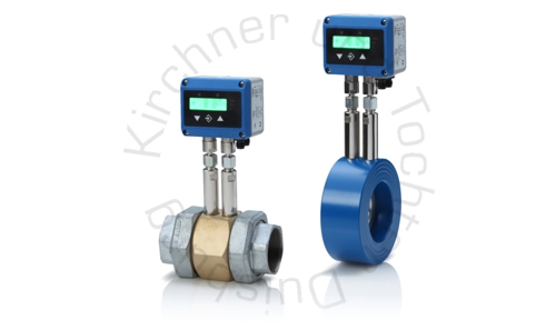
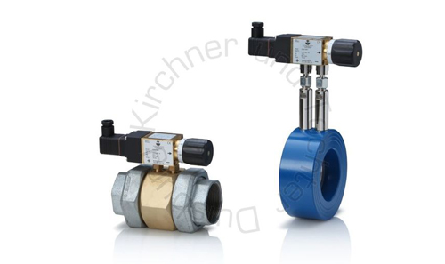
optionally available differential pressure gauge/ -transmitter in various designs
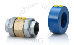
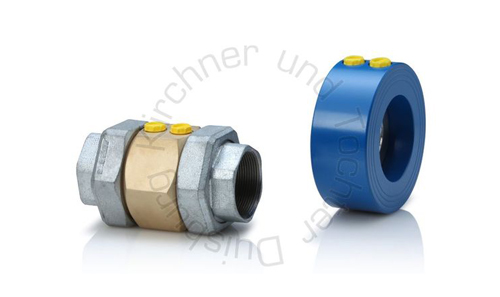
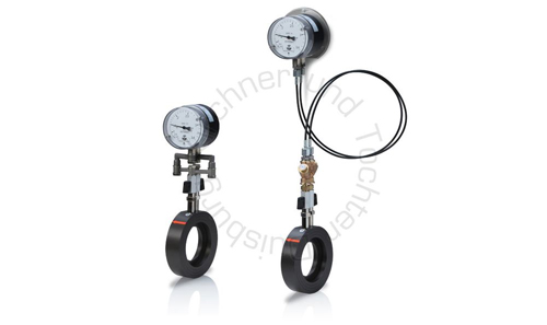
Design and applications
The DDM orifice is designed to measure and control the flow of liquids and gases.
The device works according to the principle of differential pressure.
The differential pressure at the orifice is proportional to the square of the volume rate of flow through the pipeline.
The DDM-DN orifice is fitted between flanges in the pipeline. The DDM-Rp/Gi/Ga orifice is installed in the pipeline using pipe unions or with either internal or external thread. The region of steady flow should be 6 DN upstream of the installation point and 4 DN downstream of the installation point.
The DDM orifice can be equipped with commercially available electrical or mechanical differential-pressure gauges/switches or transmitters.
Downloads
Differential pressure flow meters
DDM

DDM-DS11
DDM-EM
DDW-DS31
SMB
